This page could be considered a “blog” about my Z80 computer. I am slowly adding content as I make progress on the build.
The first board is finished!
oct 13, 2023
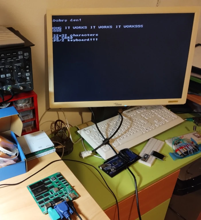
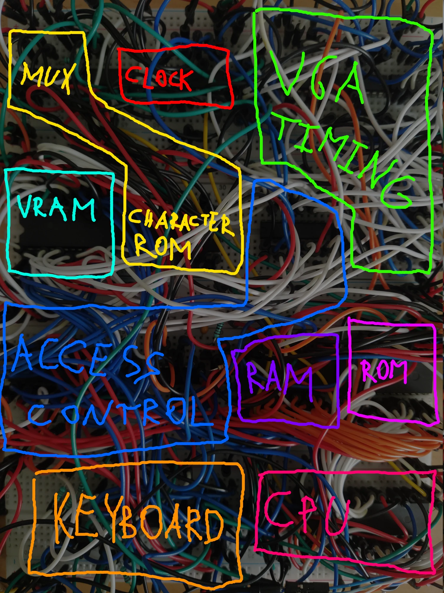
That’s right! I have finished soldering (and patching up) my first board! Now with 64k RAM, a 32k bootloader ROM, 32x32 VGA graphics, an SD card interface, and a PS/2 Keyboard! I have also realized that I am like the only person I know of, who has built a Z80 computer with all these features, without using any microcontroller, or any chip “smarter” than the Z80. The Z80 is truly the most powerful chip in my build. With the board being SMD, I consider it to be a very balanced combination of modern stadards and old hardware.
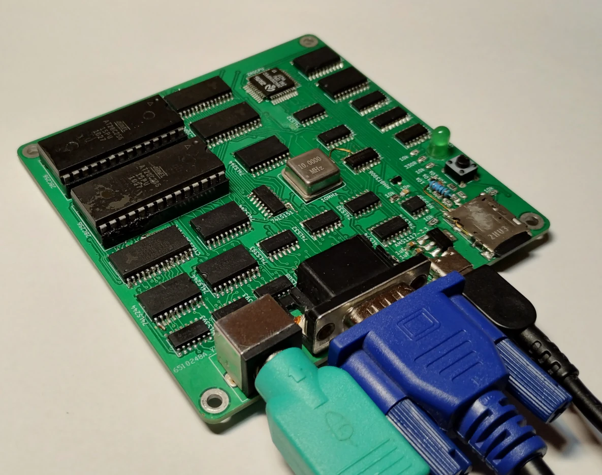
The build took so long because the first PCB I ordered had multiple design issues, so I needed to order another one. But thankfully, the new PCB works (almost) perfectly and the only issue was that I forgot to add one pull-up resistor.The reason why I destroyed THREE traces was actually because BOTH of the 74HC14 chips I ordered from a trusted european seller were faulty and I realized that too late.
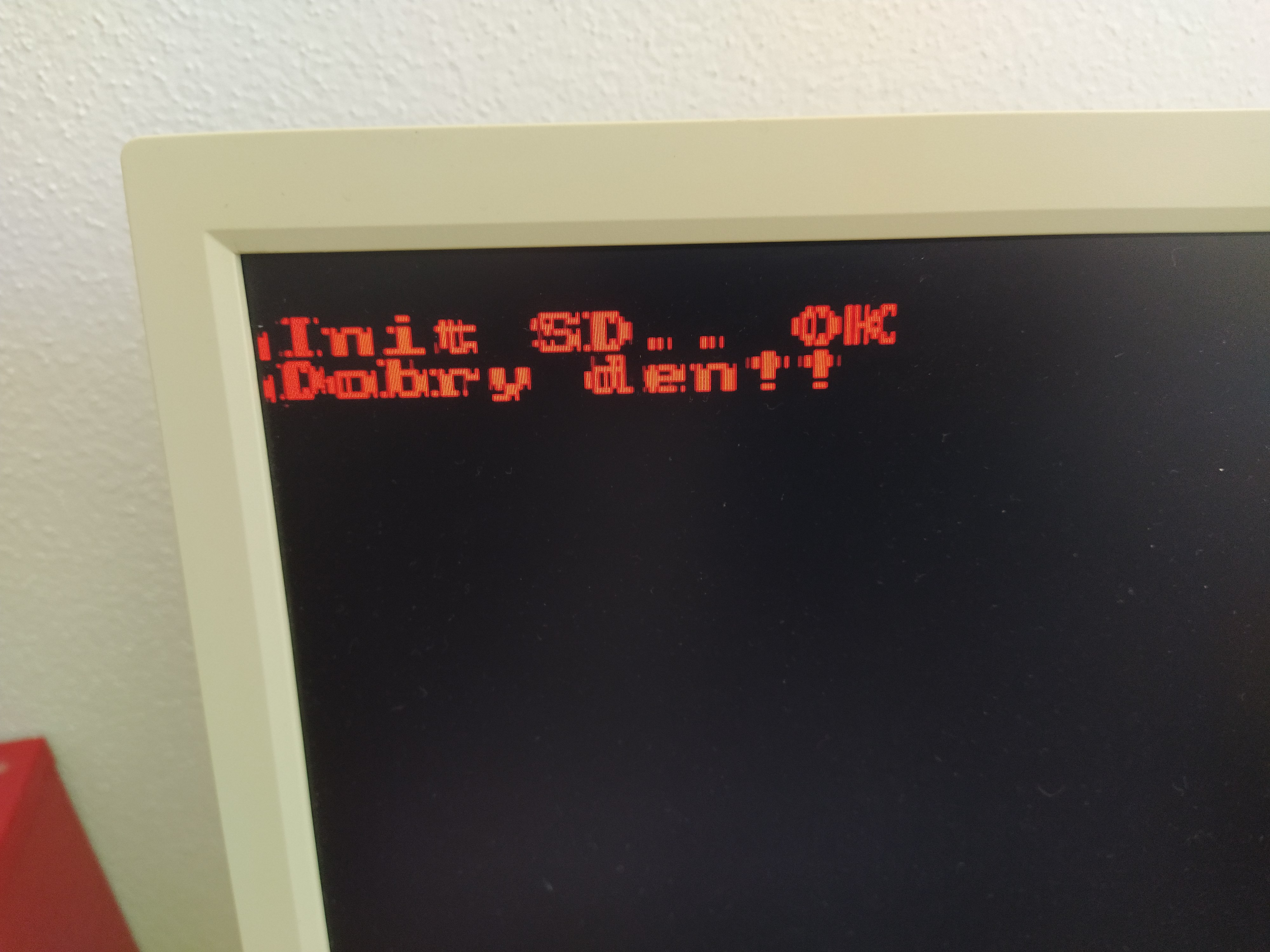
Z80 build update: booting from SD card!
aug 24, 2023
Even though my summer has been very busy, a lot of progress has actually been made on my Z80 build. I have added an SD/MMC interface, doubled the RAM, doubled the display resolution, and started working on a PCB.
The SD interface uses just simple buffers connected to the system bus paired with level shifter made of bipolar transistors because that is what I have. The level shifters are required because SD cards use 3.3V instead of the regular 5V used in most MOS chips. Data is simply bit-banged on the bus, which is pretty slow, but fast enough considering the total memory of the computer.

I have already added a FAT filesystem on the SD card, but it’s actually not used by the bootloader, instead the kernel file has to be located at a hard-coded position, which is okay for now. The way my addresses are set up allow the bootloader to have up to 32k, so I can definitely improve on it in the future.
For now, I am keeping my memory management pretty humble: upper portion of memory is always RAM, and the lower portion begins as ROM and can be switched to RAM by writing into a specific IO address. However, I have reserved whole 16k of IO addresses for memory management, so that in the future, I can implement many better memory management techniques.
With some clever timing tricks, I have also managed to quadruple the character count on the VGA adapter, without really adding to the cost of the build. My problem is, that the chips I use are too slow for something like video, so I’m really pushing them to their limits by now. The output from the video memory is delayed by almost half a character, which can be fixed by rotating the charater bits around before reaching the multiplexer, as I have mentioned last thime. The problem now is, that even the multiplexer is not fast enough for all of this. The best way I have found to reduce jitter is to actually add an inductor to the line, so that some single-pixel lines don’t even appear on the display. Another way to improve video quality os to over-volt the chips very slightly, but I definitely want to avoid that.
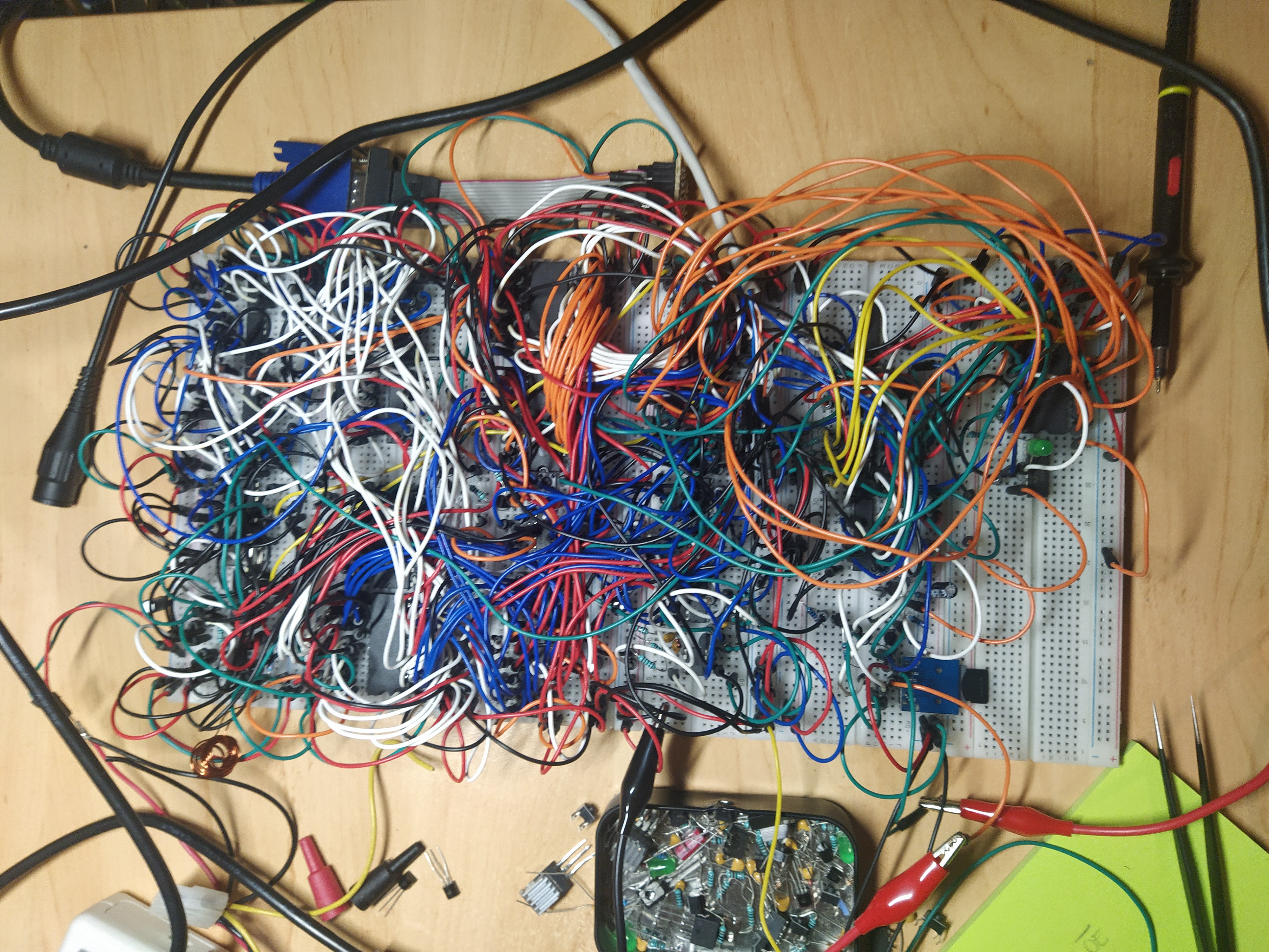
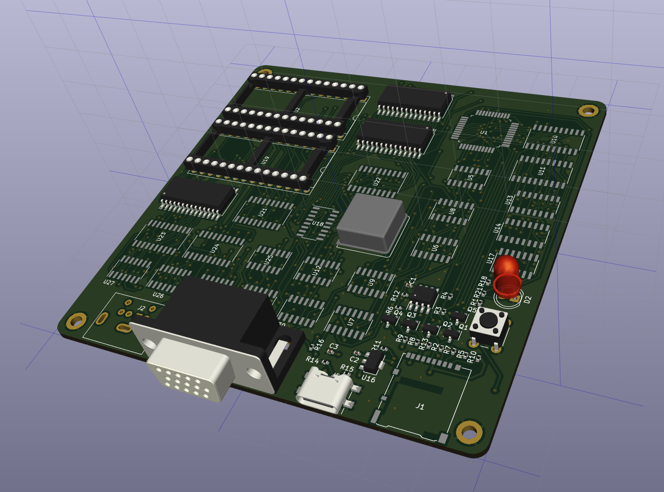
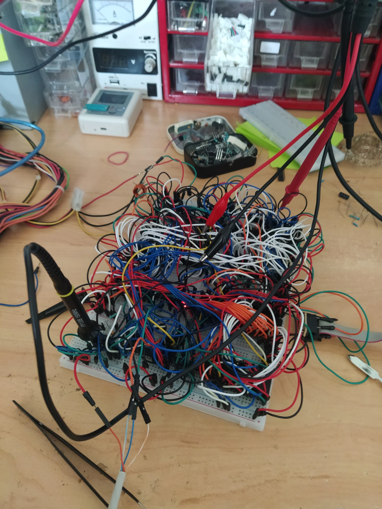
And last but not least, I am now working on like the 5th iteration of the PCB for this project. This is really my greatest priority now, because the cheap new wires I have bought from Aliexpress are more unreliable than I though and at this point, the computer is really unusable. Before making the PCB, I had to draw a schematic of the whole build in KiCad. The wires were so messy, that I ended up just rebuilding the whole thing from scratch, but this time, adding every single wire to the schematic as I was building. Then I started routing, doing like 5 whole iterations of the PCB. My PCB design is now almost ready, and I’m excited for the build!
I have buit an 8-bit computer
jun 24, 2023
School is finally over and I have found some time to work on projects. This time, I have put together some things that I made a few months back to create something at least a little bit useful. That something is an 8-bit computer based on the Z80 CPU, with VGA video output and PS/2 keyboard input.
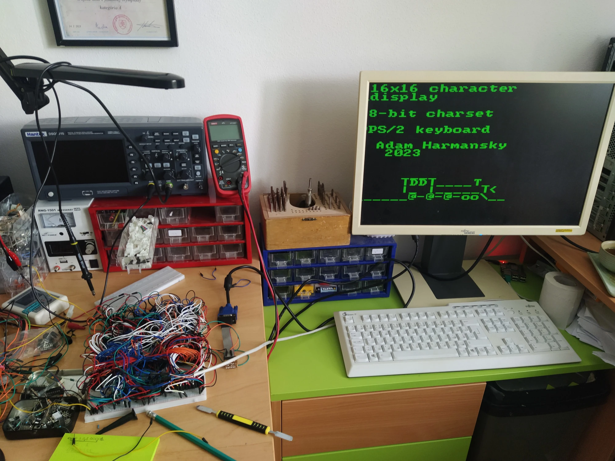
So far, the computer has 32k of RAM, 32k of ROM, a 16x16 character VGA output, and a PS/2 keyboard controller (without hardware buffering). The video memory access is simple - when the computer wants to write into video memory, it disconnects it from the video controller. The access time is so low, that the screen flashes only when text changes very rapidly. This design lets the CPU draw at any time, which is definitely more important for me than smooth graphics.
The hardest part of this build was definitely the timing. The access time of the EEPROM chip which I use for character generation is so slow, that I had to use 1 byte for 8 pixels and then multiplex it. That means, that in the ROM, one character takes up only 8 bytes of space. The output of the ram+rom is so delayed, however, that the first 2 pixels of every character were replaced by the first 2 pixels of the previous character. Luckily, I had quickly found a solution: Just rotate all the bits by 2, so that the last 2 bits will be at the start of the character. Now, when the first 2 bits are drawn at the end of the character, it’s actually the last 2 bits and everyhing looks great again.
Another challenge wat the timing of VRAM access. Normally, when
writing to IO, the IORQ and WR pins enable at
the same time, which gave the VRAM acces logic no way to disable video
controller access to the memory before the write started. This meant
that for a split-nanosecond, there was corrupt data on the bus when the
read started, which would cause the video controller to draw random
characters. My solution was to extend the pulse which disables video
controller access to the VRAM and to chop off the first part of the
WE pulse by ORing it with the CLK
signal.
The keyboard also required some tweaking by using a chain of
NOT gates, because the CLK signal was coming a
bit too soon for the 74595 shift register. To reduce the number of
NOT gates required, I used a 7414 instead of the regular
7404, because it has higher propagation delay.
The keyboard interrupts are actually generated by two 555 timers, which act as a timer, monostable circuit, and an SR-latch, all at once. That’s why I love the 555!
The software is written in my own assembler, which has some extra features which I missed in other assemblers. Then, I use my “programmer”, which is just an arduino, to program the 28C256 ROM chip and insert it into the computer. You can find the example code here. It will let you write on the display.
When I give the computer permanent storage capabilities, I will definitely create a simple OS and a very simple programming language. But using the computer practically would require me to build an MMU, to multiplex memory and have more storage space. That means that there’s still a lot of work to do until this becomes my dream computer, but it’s already on the right way to becoming something I can be proud of.